
Rigid-flex PCBs: benefits, differences and applications
What is a rigid-flex PCB? Learn the benefits, how it differs from a standard PCB, applications and design tips from a UK rigid-flex PCB manufacturer.

A rigid-flex PCB combines rigid circuit board sections and flexible circuit layers in one integrated structure. It gives design engineers a way to fit more functionality into less space, without the connectors, cables and solder joints a multi-board assembly would need.
As electronic systems get smaller, lighter and more densely packed, the traditional approach of wiring several rigid printed circuit boards (PCBs) together starts to show its limits. Every connector adds weight, takes up space and introduces another potential failure point. A rigid-flex PCB removes many of those compromises by building the interconnection into the board itself.
This guide explains how rigid-flex PCBs work, where they outperform standard boards, the sectors that rely on them, and what to consider at the design stage.
WHAT IS A RIGID-FLEX PCB?
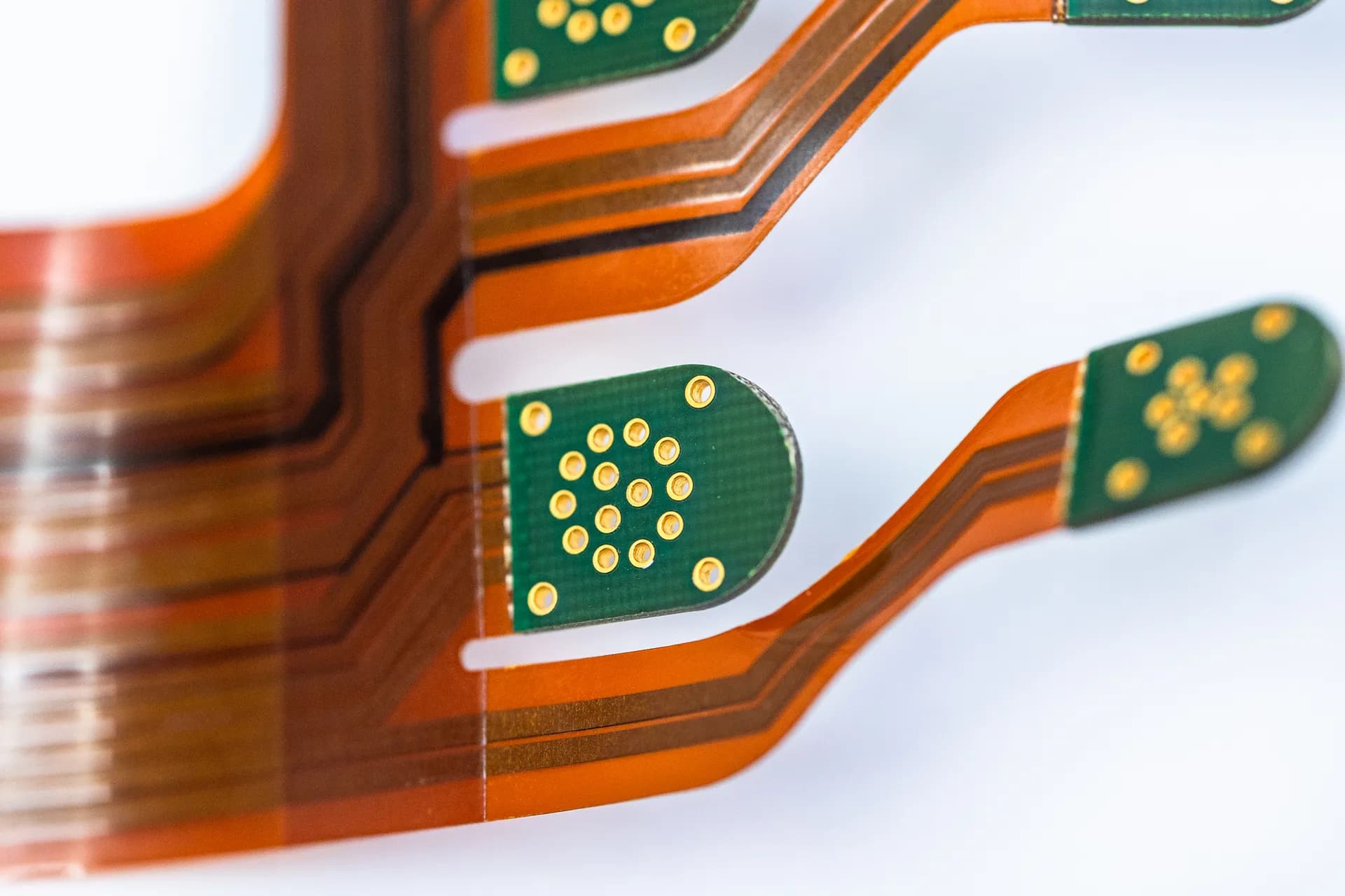
A rigid-flex PCB (also called a flex-rigid PCB) is a single board made from two types of material laminated together. Flexible layers, usually polyimide with copper conductors, run through the whole build. Rigid sections, typically FR-4 or another rigid laminate, are bonded to those flexible layers wherever components need to be mounted and supported.
Plated through-holes connect the circuitry across rigid and flexible layers, so the finished board behaves as one electrical unit. The flexible sections, protected by a polyimide coverlay rather than standard solder mask, can bend or fold to fit the product's housing. The result is a board that can wrap around corners, stack in layers or fold into a compact three-dimensional shape.

THE BENEFITS OF RIGID-FLEX PCBS
Space and weight savings. Replacing cables, harnesses and board-to-board connectors with integrated flexible sections cuts both volume and mass. For airborne, space and wearable systems, that saving can shape the whole product design.
Fewer interconnection failure points. Connectors and solder joints are among the most common sources of field failures. A rigid-flex PCB removes many of them, which reduces the risk of intermittent faults caused by loosening, corrosion or poor mating.
Better resistance to vibration and shock. With fewer heavy connectors and loose cables, the assembly has less mass to move under vibration. The flexible sections also absorb some mechanical stress rather than transferring it to solder joints.
Three-dimensional packaging freedom. Rigid-flex lets engineers design around the enclosure, not the other way round. Boards can fold into tight housings, follow curved surfaces or stack vertically.
Improved signal integrity. Shorter, continuous signal paths with fewer transitions support cleaner signals. Controlled impedance can be designed into the flexible layers, which matters for high-speed digital and RF circuits.
Simpler assembly and lower system cost. A rigid-flex PCB usually costs more per unit than a standard board. However, fewer parts, fewer assembly steps and less inspection often lower the total cost of the finished system, particularly once testing and field reliability are factored in.
| Specifications | Standard rigid PCB |
|---|---|
| Structure | Rigid laminate throughout |
| Materials | Typically FR-4 or other rigid laminates |
| Interconnection | Connectors, cables or harnesses between boards |
| Form factor | Flat, fixed shape |
| Surface protection | Solder mask |
| Design rules | Well established, fewer mechanical constraints |
| Manufacturing | Conventional lamination and processing |
| Unit cost | Lower |
| Specifications | Rigid-Flex PCB |
|---|---|
| Structure | Rigid sections joined by flexible layers in one build |
| Materials | Polyimide flex layers combined with rigid laminates |
| Interconnection | Integrated flexible circuitry, no board-to-board connectors |
| Form factor | Can bend, fold and fit three-dimensional spaces |
| Surface protection | Solder mask on rigid areas, coverlay on flex areas |
| Design rules | Bend radius, transition zones and stack-up balance all matter |
| Manufacturing | Multiple lamination stages, specialist materials and tighter process control |
| Unit cost | Higher, often offset by lower system and assembly cost |
The biggest difference sits at the design stage. A standard PCB is mostly an electrical design problem. A rigid-flex PCB is an electrical and mechanical design problem at the same time, because the board has to survive being bent, folded or flexed in service. That's why early conversations between the design engineer and the manufacturer have more influence on a rigid-flex project than on almost any other board type.
APPLICATIONS FOR RIGID-FLEX PCBS
Rigid-flex PCBs appear wherever space is tight, weight matters and failure is costly. That makes them a natural fit for high-reliability sectors.
Aerospace - Avionics, flight control electronics and in-cabin systems benefit from lower weight and fewer connectors, both of which support long service lives under constant vibration.
Defence & Security - Guidance systems, radar modules, rugged handheld equipment and communications hardware use rigid-flex to pack complex electronics into compact, shock-resistant enclosures.
Space - Satellite payloads and subsystems face strict mass budgets and can't be repaired once launched. Removing connectors and cabling cuts weight and reduces the number of potential failure points.
Medical & Life Sciences - Wearable monitors, imaging probes, surgical instruments and diagnostic equipment all demand small form factors. Rigid-flex allows electronics to follow the shape of a handheld or body-worn device.
Automotive & Transport - Camera modules, sensors, lighting and driver-assistance electronics use rigid-flex to fit inside compact housings while coping with vibration and temperature cycling.
Motorsport - Steering wheel electronics, telemetry and data-logging systems need low weight and resistance to extreme vibration, with minimal packaging space.
Energy & Industrial - Robotics, instrumentation and control systems use rigid-flex where boards need to move with mechanical assemblies or fit into constrained enclosures.
DESIGNING A RIGID-FLEX PCB FOR MANUFACTURE
Good rigid-flex design starts with decisions that are hard to change later. These are the areas our engineers most often review with customers before production:
- Define how the flex will be used - A board bent once during installation (static flex) has very different requirements from one that flexes repeatedly in service (dynamic flex). IPC-2223, the design standard for flexible and rigid-flex boards, gives minimum bend-radius guidance based on flex thickness and layer count.
- Keep vias and plated holes out of bend zones - Keep them clear of the rigid-to-flex transition too, where mechanical stress is highest.
- Route conductors perpendicular to the bend line - Stagger traces on adjacent flex layers and use curved rather than sharp corners to spread stress.
- Use hatched copper planes in flex areas - Solid copper stiffens the flex and increases the risk of cracking.
- Balance the stack-up - Symmetrical constructions, usually with flex layers near the centre, help control warpage through multiple lamination cycles.
- Agree coverlay openings and stiffeners early - Stiffeners support connectors and components on flexible sections, and their placement affects both assembly and reliability.
Bringing your manufacturer into the conversation before layout is frozen is the most effective way to reduce cost and risk. Our engineering team reviews stack-ups, material choices and rigid-to-flex transitions at the front end, so problems are solved on screen rather than on the production floor.
RIGID-FLEX PCB MANUFACTURING AT EXCEPTION PCB
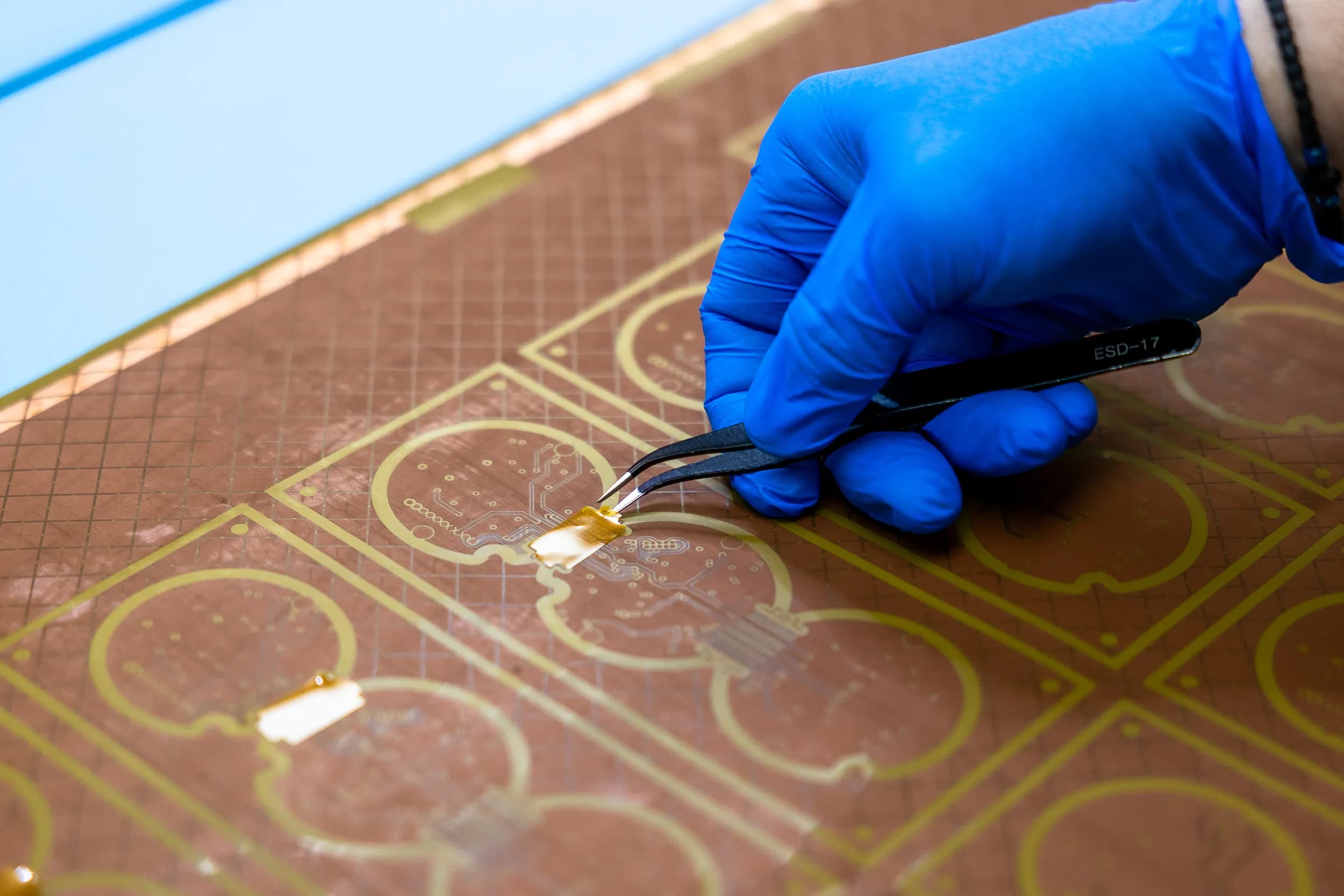
Flex & Rigid-Flex is one of six advanced technologies we manufacture at our facility. Our capability covers:
- Rigid-flex builds of up to 14 layers (10 rigid and 4 flex) as standard, up to 24 layers (20 rigid and 4 flex) at advanced level, and 25+ layers at research and development (R&D) level
- Pure flex builds of up to 4 layers as standard
- Rigid-flex combined with high-density interconnect (HDI), laser-drilled microvias and copper-via-fill for dense, complex designs
- Quick-turn prototypes, new product introduction (NPI) and low-to-medium volume production
Every board is built within a quality system certified to AS9100 Rev D and ISO 9001:2015, to IPC Class 2 or Class 3 requirements, and receives 100% electrical test before dispatch.
Technology alone doesn't produce a good rigid-flex PCB. Our engineers, technicians and quality team bring decades of experience in complex constructions, working alongside customers from first design review through to delivery. As part of the Connexion Technologies group, we combine that heritage with continued investment in UK manufacturing capability.
TALK TO OUR ENGINEERS ABOUT YOUR RIGID-FLEX PCB
Whether you're moving from a multi-board assembly to rigid-flex or refining a complex HDI rigid-flex design, our engineering team can review your design before production starts. Get in touch or request a quote to discuss your project.
FREQUENTLY ASKED QUESTIONS
What is the difference between a flex PCB and a rigid-flex PCB?
A flex PCB is flexible throughout and usually needs connectors or stiffeners to attach to other boards. A rigid-flex PCB combines flexible and rigid sections in one board, so components can be mounted on rigid areas while flexible sections replace the interconnections.
Are rigid-flex PCBs more expensive than standard PCBs?
Yes, per unit. The materials and multi-stage lamination process cost more. However, removing connectors, cables and assembly steps often lowers the total system cost.
How many layers can a rigid-flex PCB have?
It depends on the design and manufacturer. At Exception PCB, standard rigid-flex builds go up to 14 layers, advanced builds up to 24 layers, and R&D projects beyond 25 layers.
Which standards apply to rigid-flex PCBs?
IPC-2223 covers design guidance for flexible and rigid-flex boards, while IPC-6013 sets the qualification and performance requirements. The IPC class (Class 2 or Class 3) should be agreed at the start of the project.
Can a rigid-flex PCB flex repeatedly in service?
Yes, if it's designed for dynamic flexing. That calls for larger bend radii, careful conductor routing and suitable copper and material choices, all of which should be agreed with your manufacturer early.